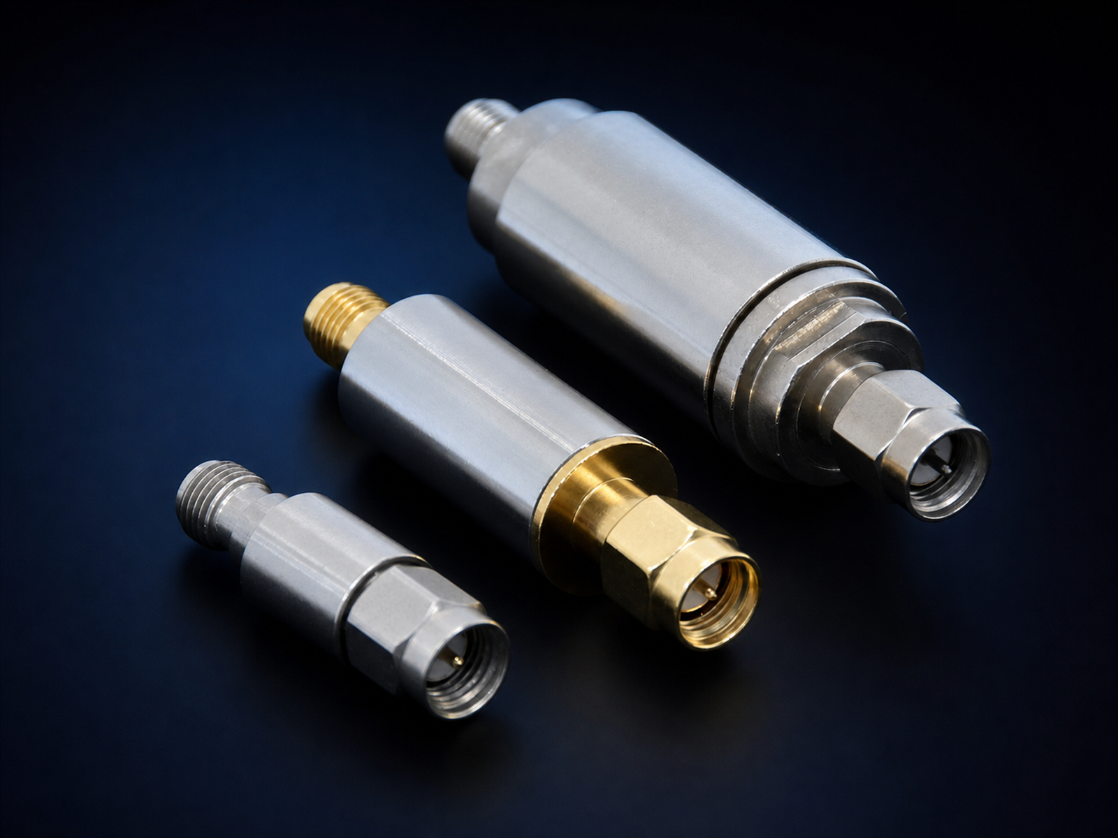
How to Specify a Custom RF Filter: 8 Points That Get You a Quote Faster
Most RF filter quotations stall for the same reason: the inquiry arrives with a center frequency and nothing else. The supplier has to send three rounds of questions before an engineer can propose a topology, and by then the project schedule has already moved.
This checklist covers the eight specifications that determine whether a custom filter can be quoted in one pass. It is written for design engineers and purchasing teams who need a usable answer quickly, not a brochure.
1. Passband frequency range, not just center frequency
A center frequency of 2.45 GHz tells us very little on its own. A filter with a 20 MHz passband and a filter with a 400 MHz passband at the same center frequency are different products, built with different technologies and priced differently.
State the passband as a range with defined edges: for example 2400 to 2500 MHz. If the requirement comes from a standard, name the standard and the channel plan. If the passband edge is defined by a return loss limit rather than a hard cutoff, say so.
2. Bandwidth and skirt steepness
Bandwidth alone is not enough. The transition from passband to stopband, usually described as the shape factor or the rejection at a specified offset, decides whether a compact LC design is sufficient or whether the application needs a cavity or thin-film approach.
A practical way to express this: “Rejection greater than 40 dB at 2350 MHz and at 2550 MHz.” That single sentence tells a filter designer more than a paragraph of description, because it fixes the required selectivity.
3. Insertion loss budget
Insertion loss in the passband is a direct trade against size, selectivity and cost. A specification of “as low as possible” pushes the design toward larger resonators and a higher price. A number gives the designer room to optimize.
Give a target and an acceptable maximum, for example “typical 1.5 dB, maximum 2.0 dB over the passband at 25 degrees C.” Also state whether the loss budget includes connector and cable losses in your measurement setup, since this is a common source of disagreement at acceptance testing.
4. Rejection requirements across the full stopband
Out-of-band rejection is where most specifications are incomplete. Interference sources are rarely at one frequency. If the system must survive a nearby transmitter, a radar pulse or a harmonic of its own local oscillator, name those frequencies and the attenuation needed at each.
Also clarify what happens far from the passband. A filter that reaches 60 dB at 2.6 GHz may fall back to 30 dB at 6 GHz because of spurious responses. If wideband rejection matters, a cascaded design or an additional low-pass stage may be required.
5. Impedance and connector interface
Fifty ohm is the default, but not universal. State the system impedance and the connector type on both ports: SMA, N-type, BNC, SMP, or a surface-mount pad for board-level integration. Mixed interfaces are common in test equipment and should be specified explicitly.
For drop-in or SMT parts, provide the footprint or a mechanical drawing reference. A filter that fits electrically but not mechanically is still a redesign.
6. Power handling
Power handling determines the resonator size and the internal construction. A receive-path filter may see milliwatts; a transmit-path filter in the same system may see tens of watts, and the two cannot share a design.
Give continuous average power and peak power separately, plus the duty cycle if the signal is pulsed. For pulsed radar and amplifier chains this is the difference between a part that survives and a part that fails in the field.
7. Operating temperature range
Filter center frequency drifts with temperature. The amount depends on the technology: cavity and dielectric resonators are comparatively stable, LC designs with high-Q capacitors are less so. Specify the ambient range the part must operate in, and whether the electrical performance must hold across the full range or only at room temperature.
For outdoor, airborne or automotive-adjacent installations, state the range up front. It changes the material selection and therefore the price.
8. Mechanical envelope and environment
Available volume is often the hardest constraint in a filter design. Provide the maximum outline dimensions and, if relevant, the mounting method and the direction of the connectors. Mention any shock, vibration, humidity or ingress protection requirement that the housing must satisfy.
What a complete inquiry looks like
Assembled together, the eight points produce an inquiry a filter engineer can work with in a single pass:
- Passband: 2400 to 2500 MHz
- Rejection: greater than 40 dB at 2350 MHz and 2550 MHz
- Insertion loss: 1.5 dB typical, 2.0 dB maximum
- Impedance and connectors: 50 ohm, SMA female both ports
- Power: 10 W average, 100 W peak, 10 percent duty cycle
- Temperature: minus 40 to plus 85 degrees C, full performance
- Envelope: 60 by 40 by 20 mm maximum, four M3 mounting holes
That takes about ten minutes to write and usually removes two weeks of back-and-forth. If some values are still open, send the ranges you are considering and mark them as provisional. A supplier who understands the application can often propose a topology and flag the trade-offs before the design is frozen.
Where the technology choice fits
Once the electrical requirements are clear, the filter family follows from them. Lumped-element LC designs suit lower frequencies and moderate selectivity in compact packages. Thin-film filters serve higher frequencies where repeatable, tight-tolerance response matters. Cavity filters deliver high selectivity and low loss at the cost of volume. Dielectric resonators occupy the middle ground for narrowband, temperature-stable requirements.
Describing your constraints, rather than naming a technology, usually produces a better proposal, because the supplier can select the family that meets the requirement at the lowest cost.
If you have a specification in progress, send it through the RFQ form or start a conversation on WhatsApp. Rough numbers are enough to begin.
Need a filter quoted?
Send the passband, rejection target and quantity. We will confirm the topology and lead time.